
Assembly
Assembly
Section titled “Assembly”Because this subsystem contains a static part and a moving part, we want to separate them into rigid (no movement) assemblies, then combine them at the top level. This makes load times significantly faster.
Base Assembly
Section titled “Base Assembly”Create an assembly for the static parts, insert the parts and origin cube from the part studio with the green checkmark, and group them together. Fasten the origin cube to the origin. Add the rest of the parts from the part studio, MKCAD, and standard content, using replicate and patterns when you can.

Arm Assembly
Section titled “Arm Assembly”Create an assembly for the arm portion of the mechanism and do the same thing as above to complete the assembly and make it rigid.

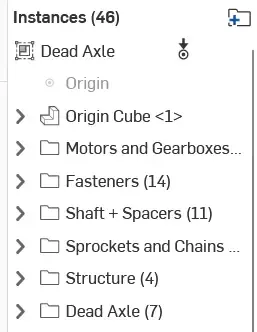
Below is an example of the instance list of a rigid assembly. Notice the icon in the top left indicating it’s rigid. You can tell what can still move in the assembly by a “degree of freedom” icon (3 arrows to indicate the 3 axis.)
Top Level Assembly
Section titled “Top Level Assembly”Now create a top level assembly and insert the static assembly (fasten to the origin) and intake arm assembly. Create a revolute mate between the mate connectors from the origin cubes in both assemblies and add a limit to it. This completes the deadaxle pivot assembly.
