
Exercise 3: Gear and Belt Gearbox
Exercise 3: Belt and Gear Transmission
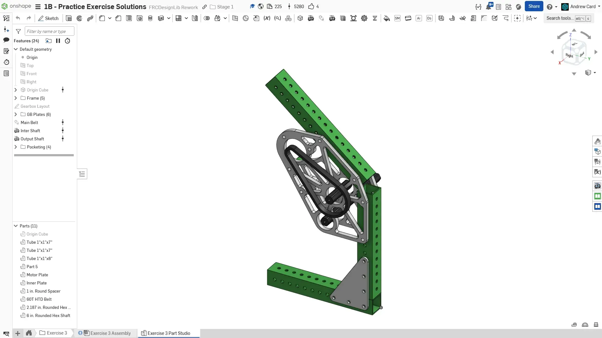
Section titled “Exercise 3: Belt and Gear Transmission”In this exercise, you will be modeling a two stage gearbox that uses gears and belts. This gearbox will also include elements like frame and gussets, which you previously learned in Stage 1A. The goal of this exercise is to continue to ramp up your modeling skills.
Always make sure to fully define your sketches, rename your features, and keep your feature and instance trees organized with folders.
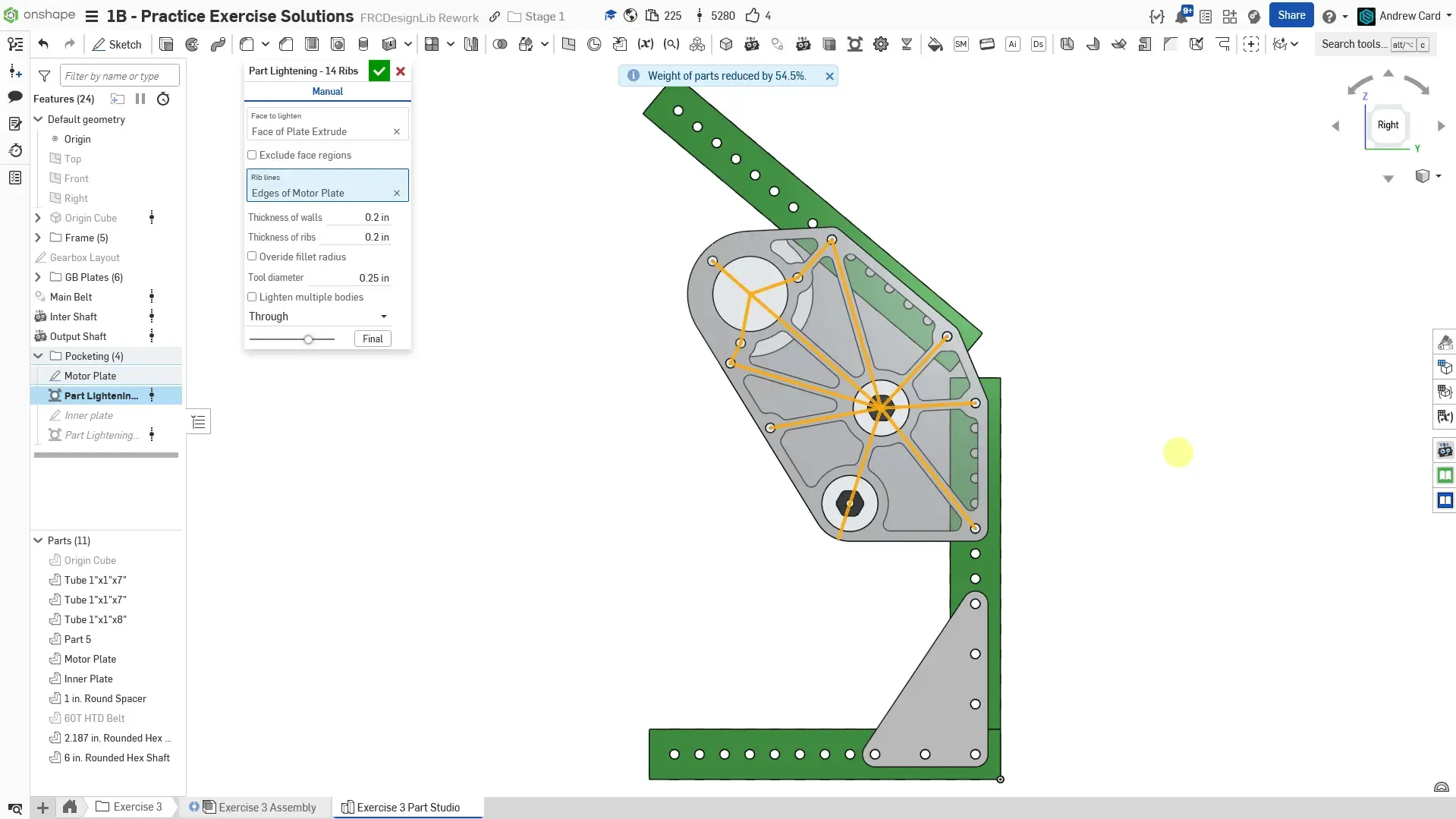
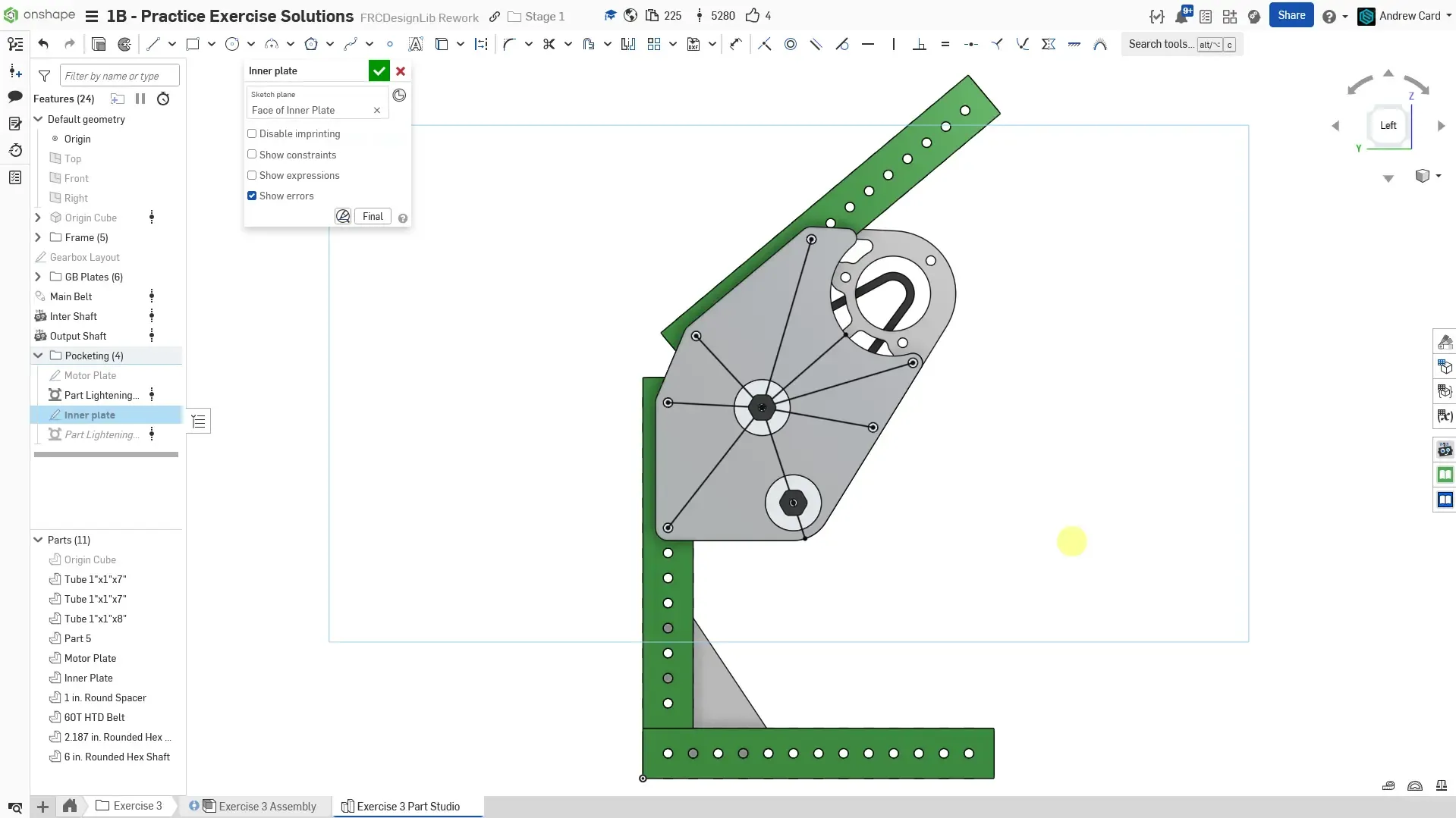
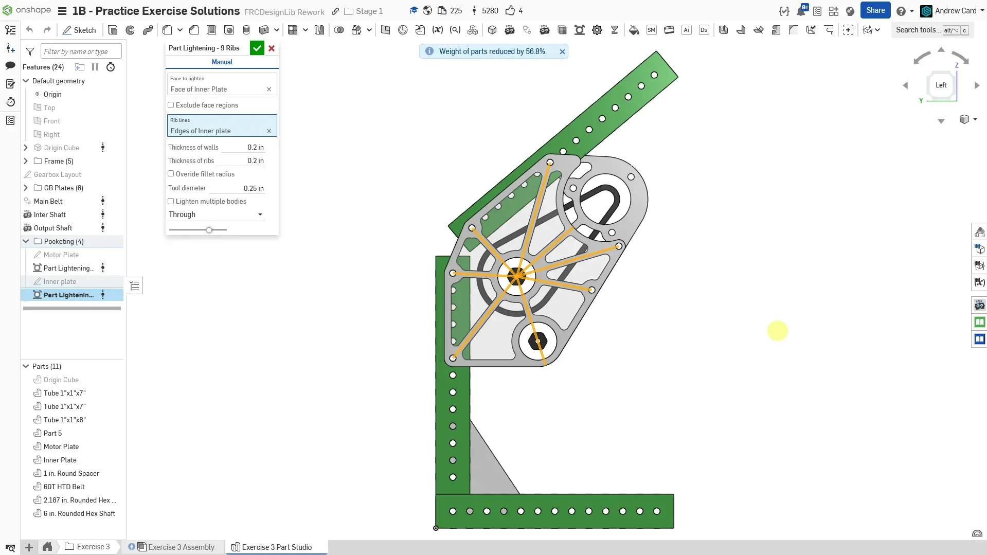
Part Studio Instructions
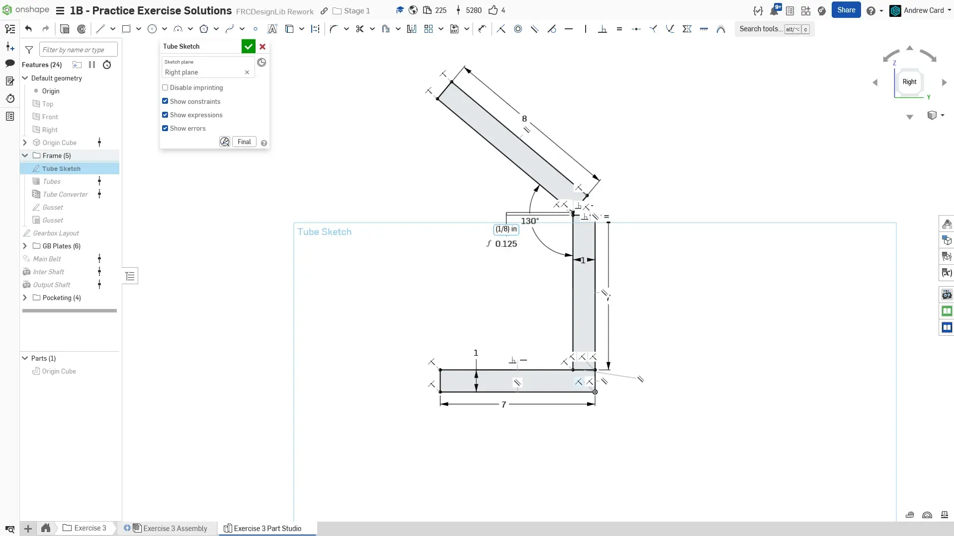
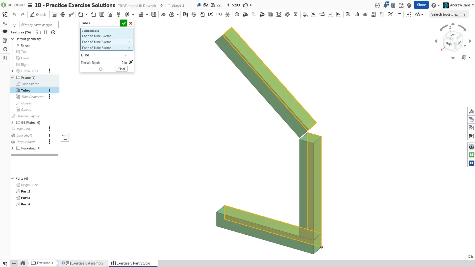
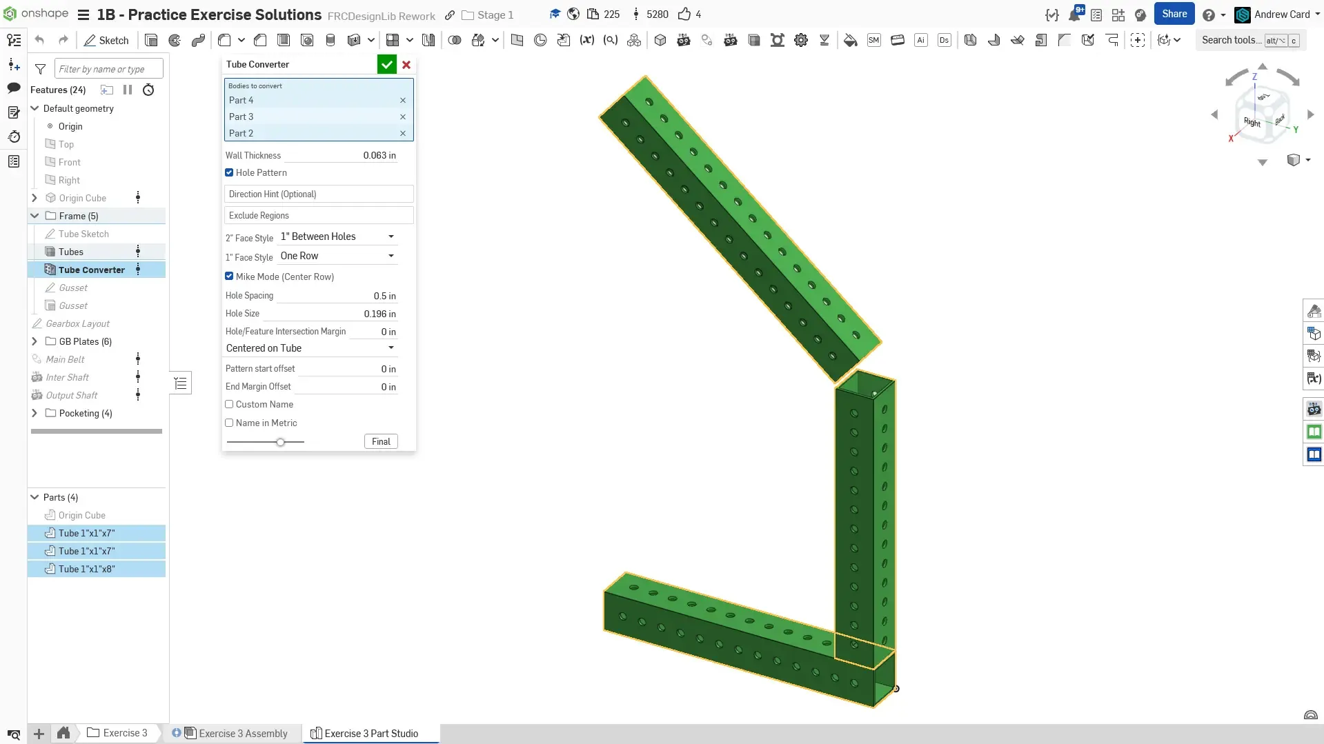
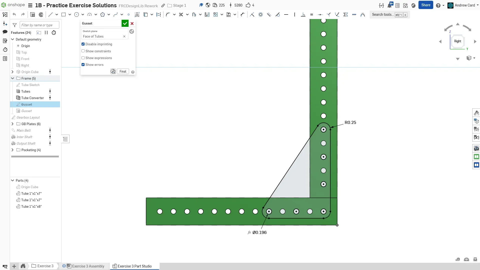
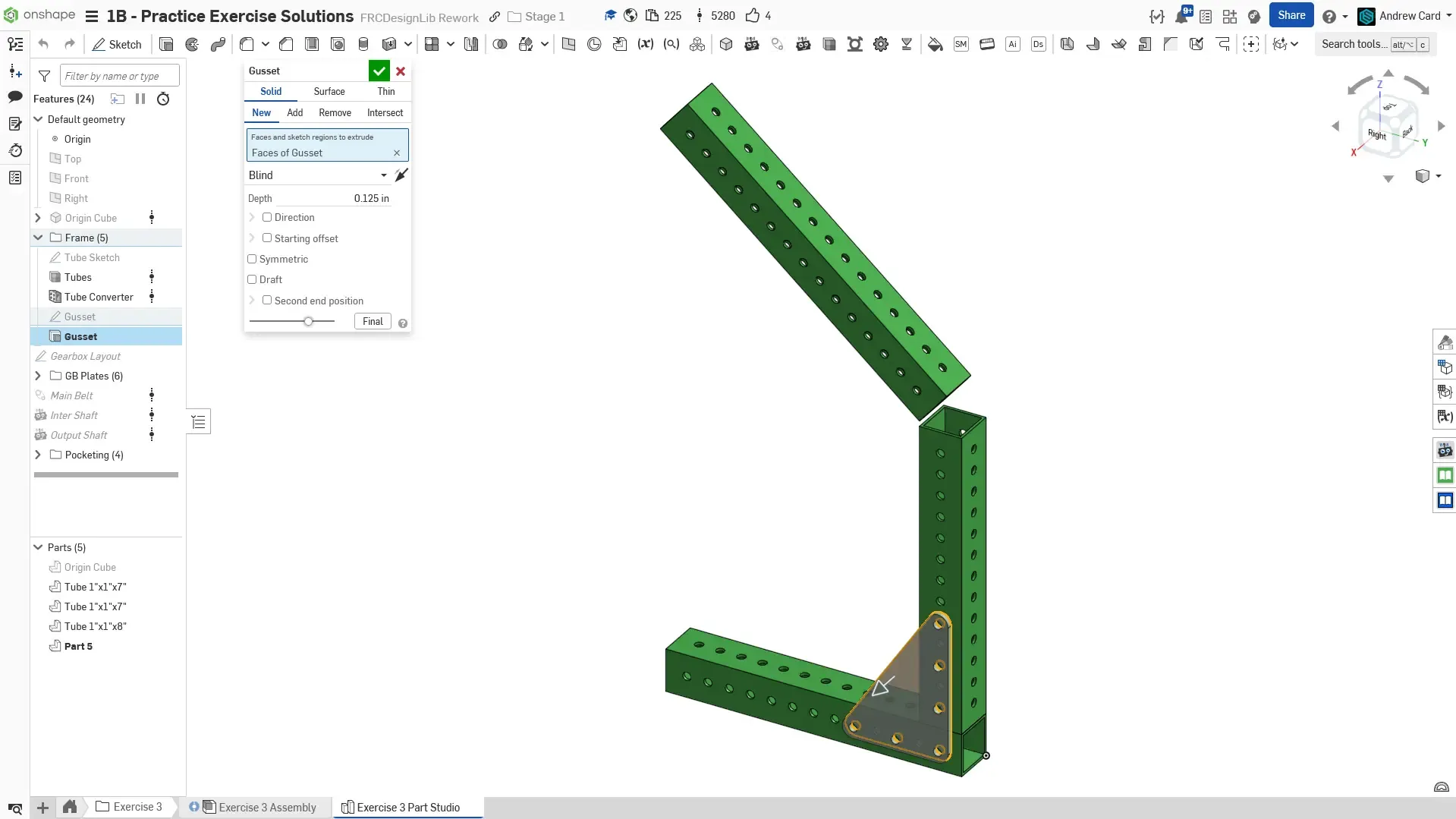
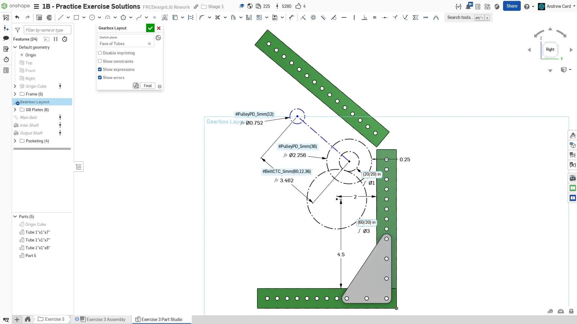
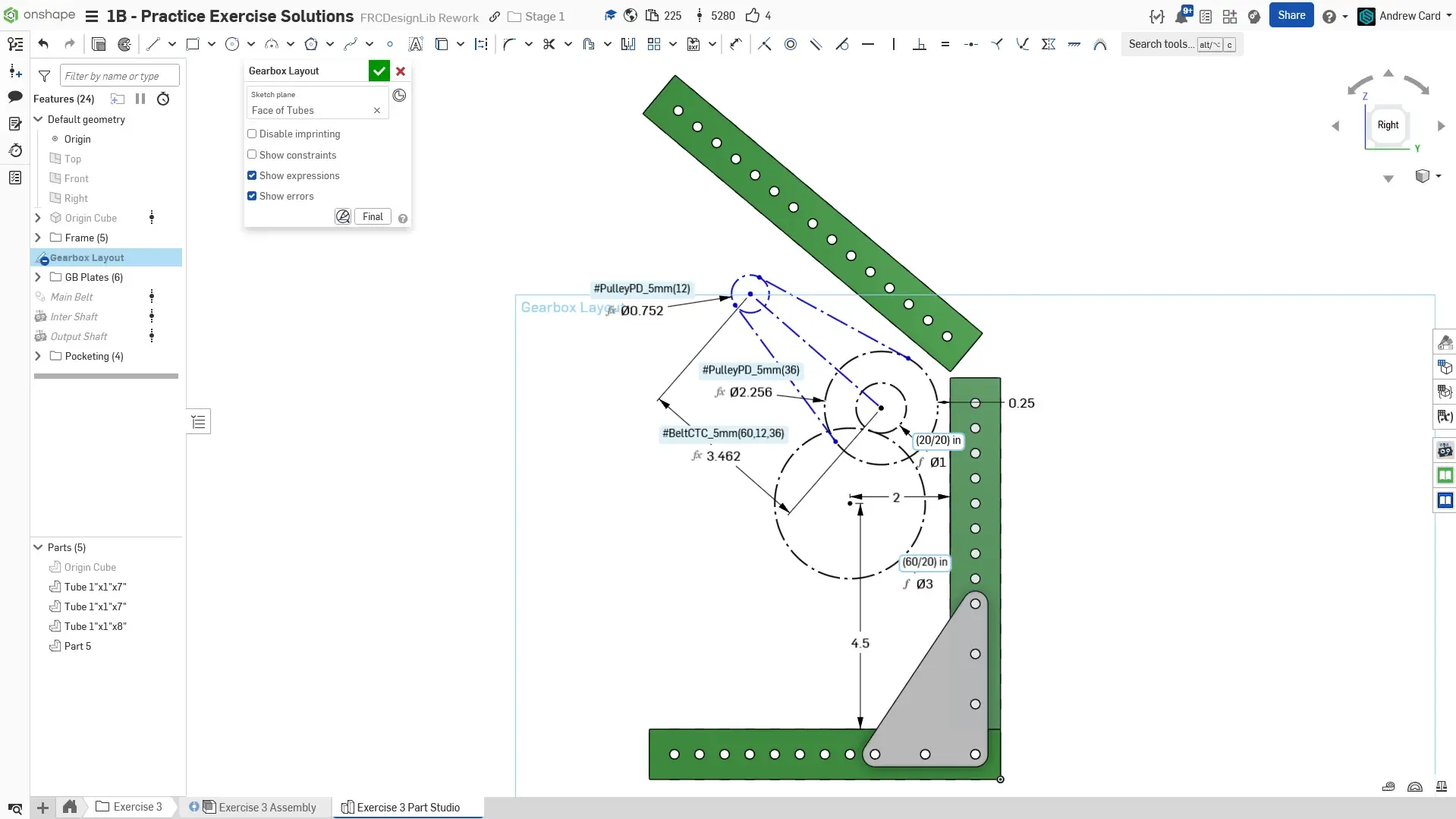
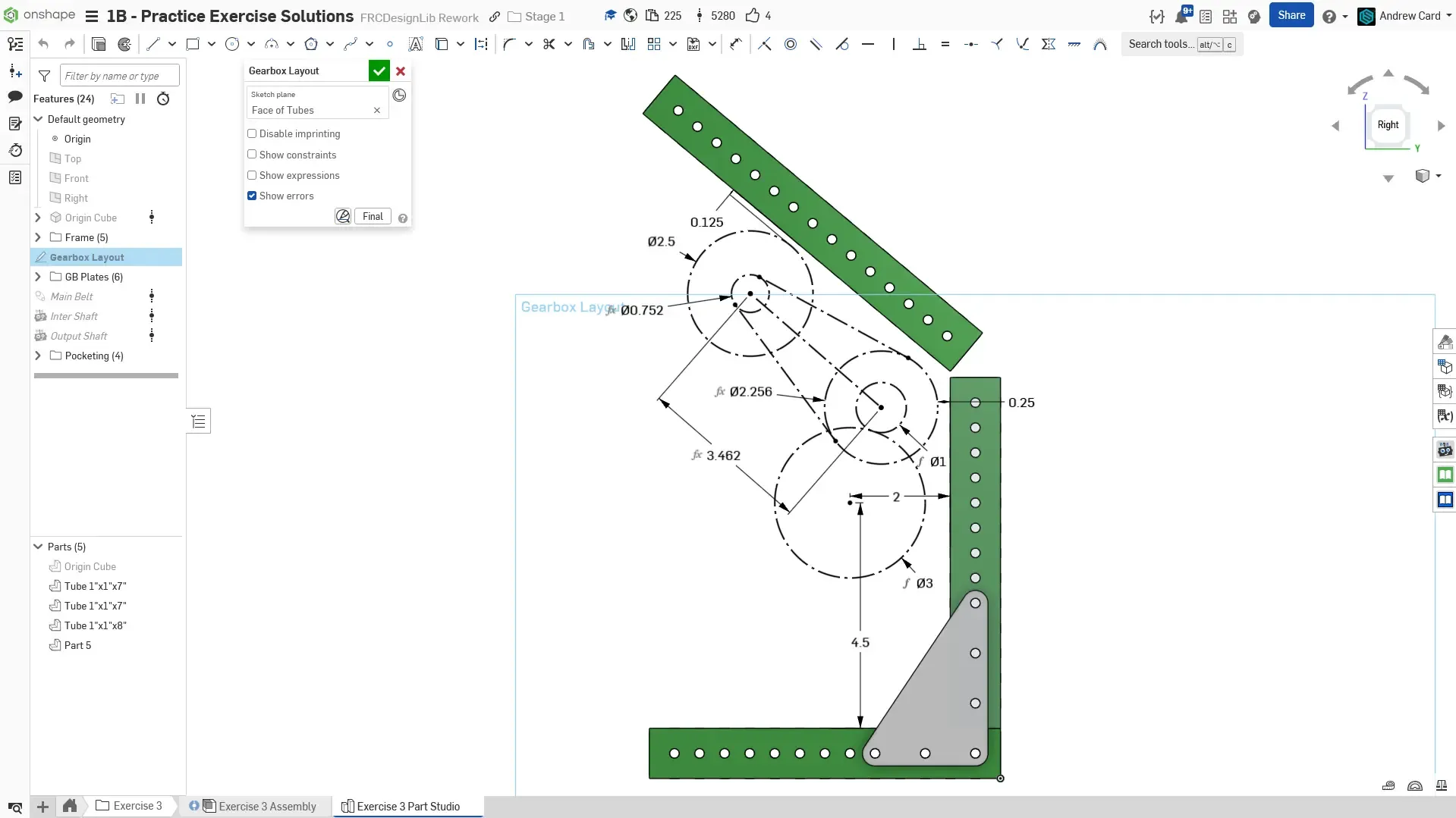
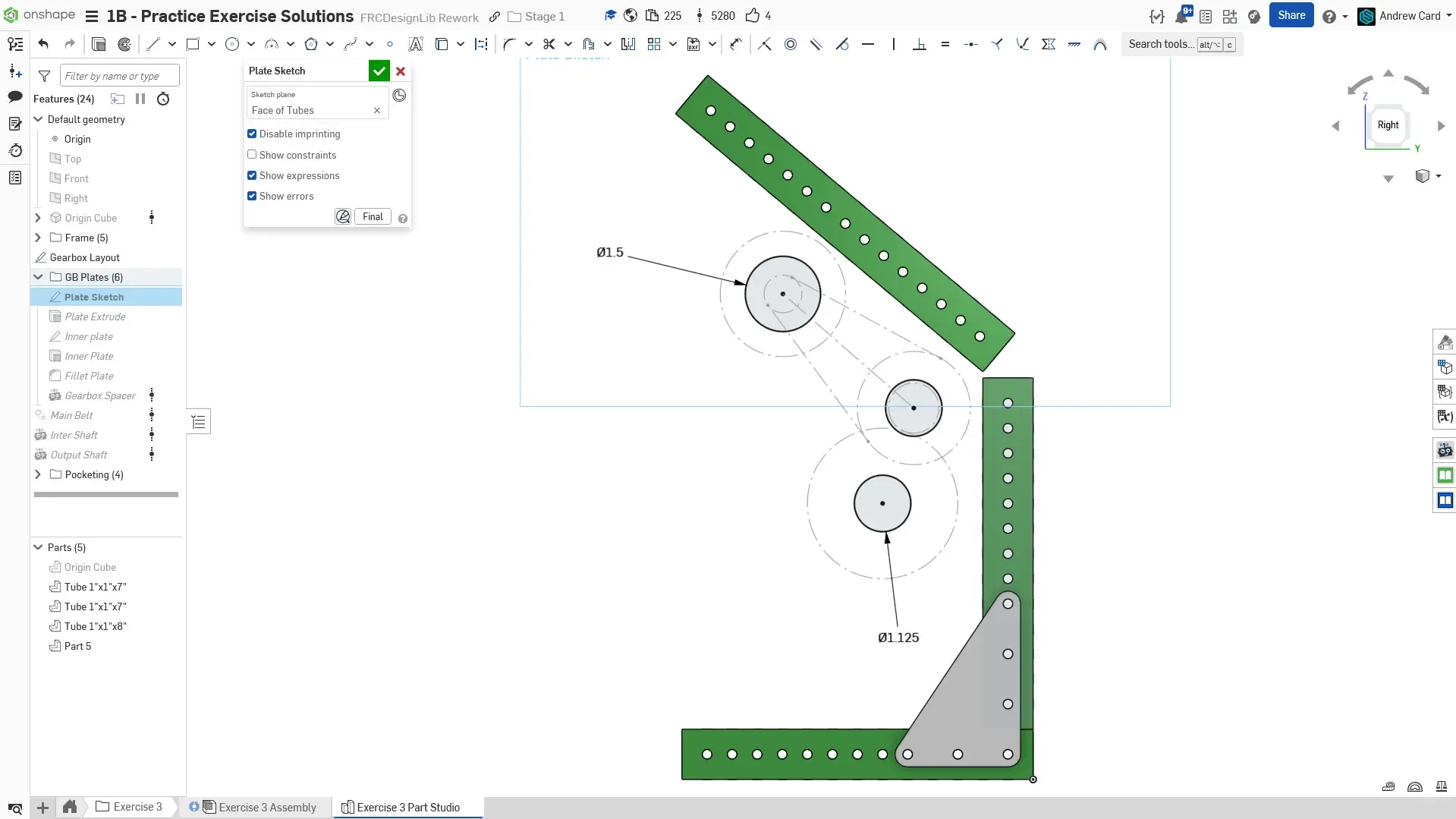
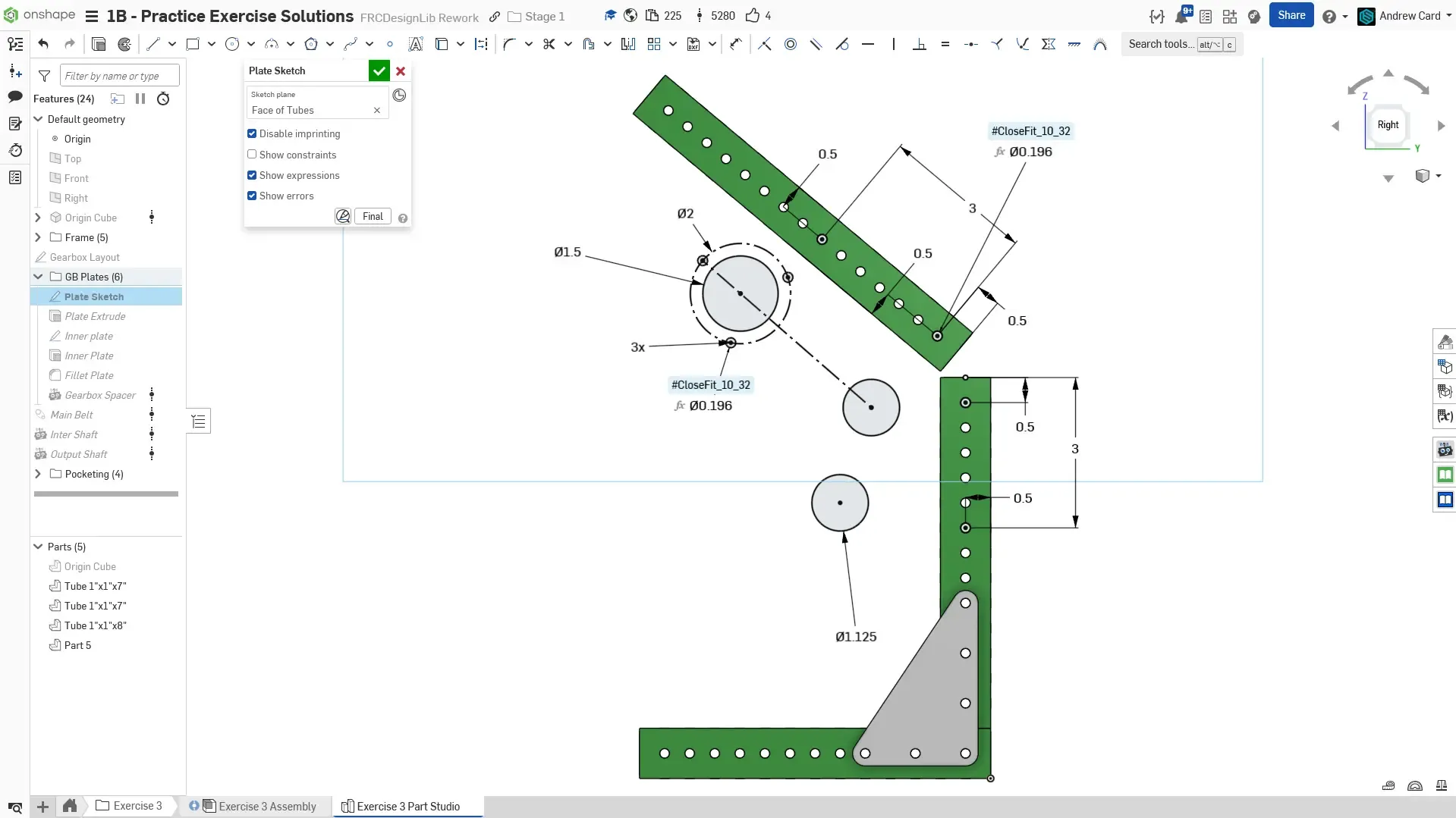
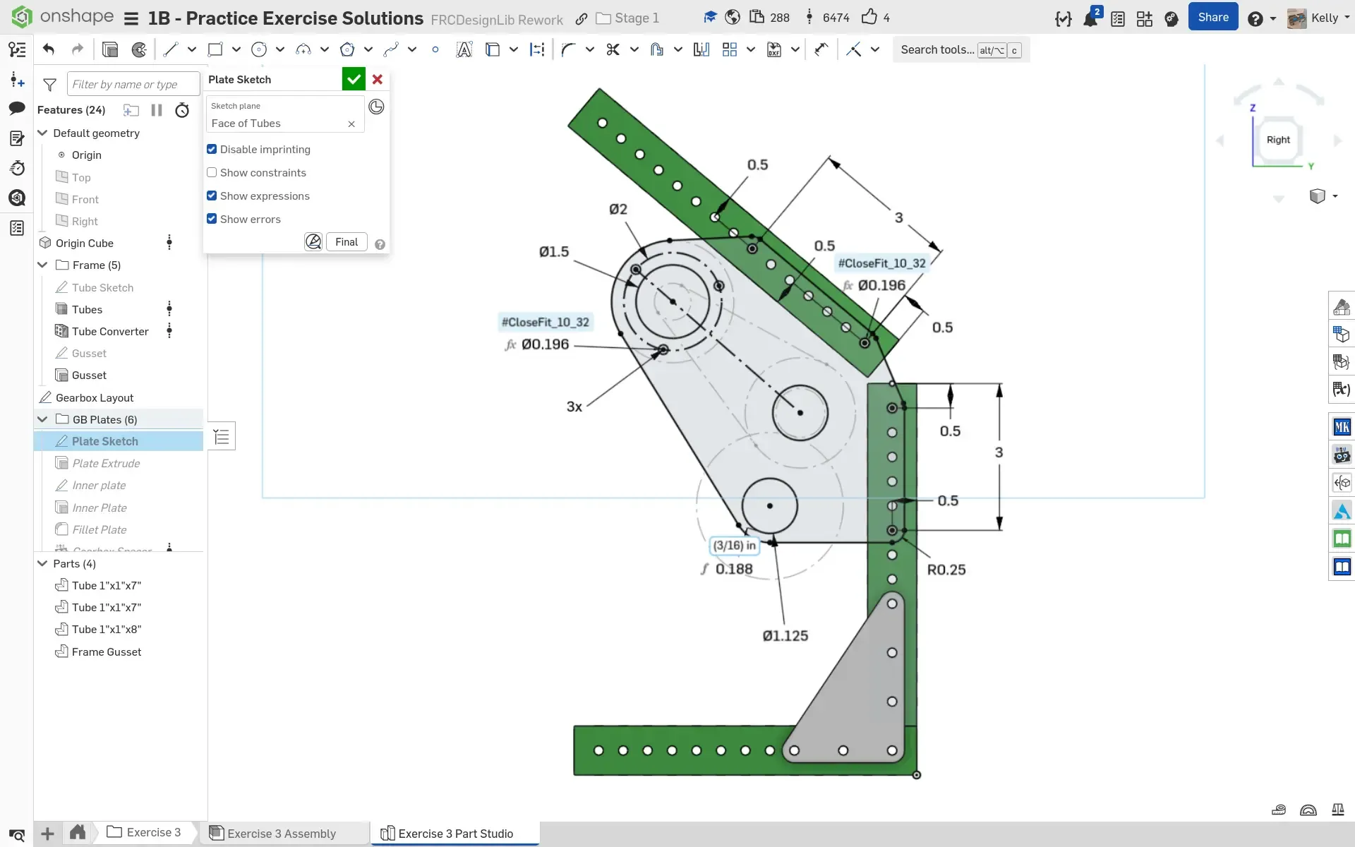
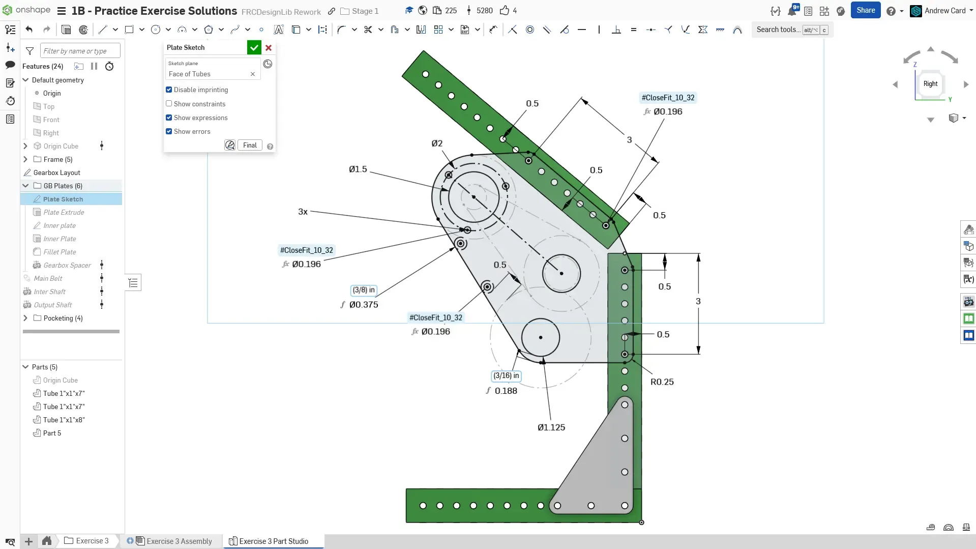
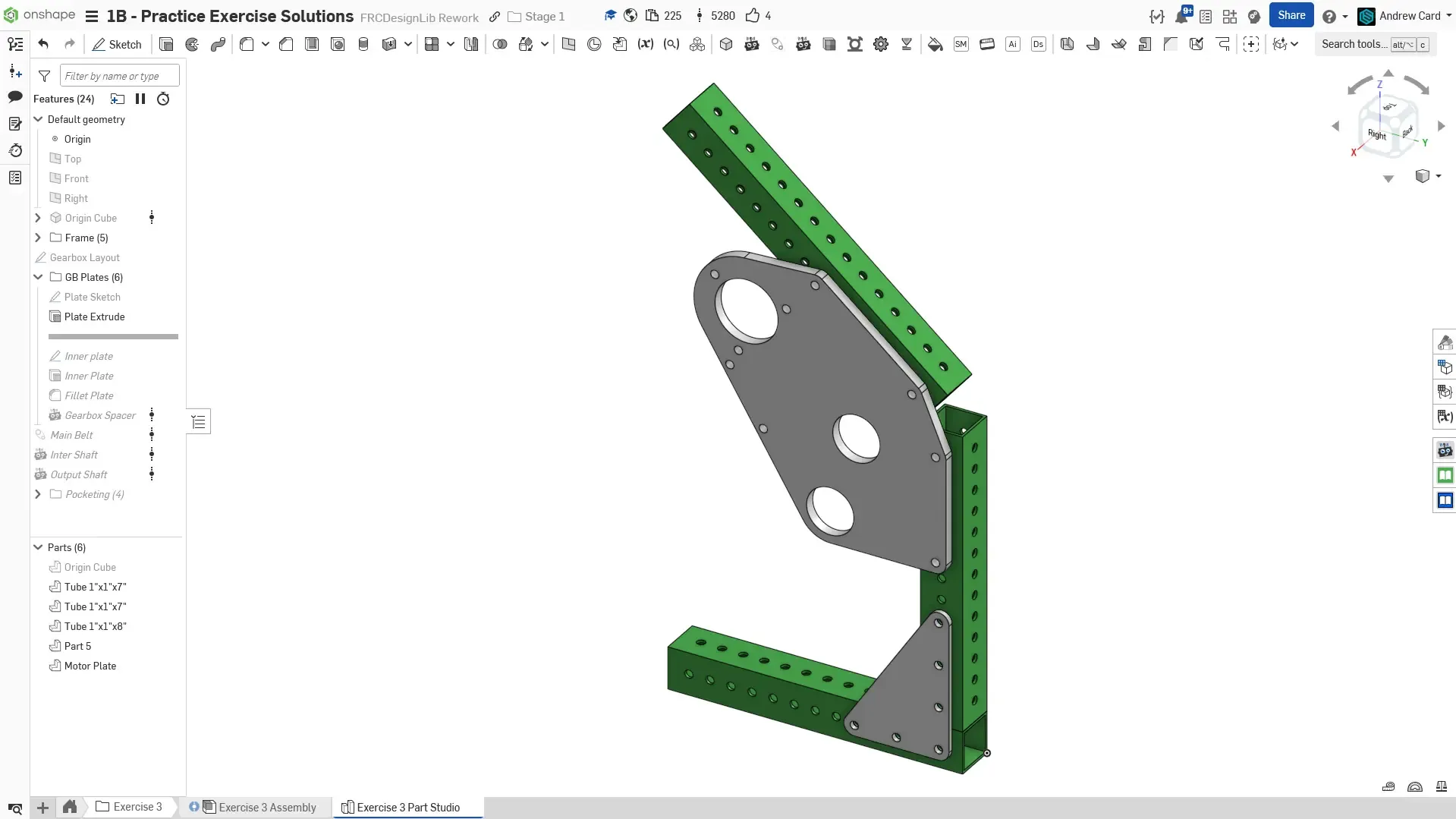
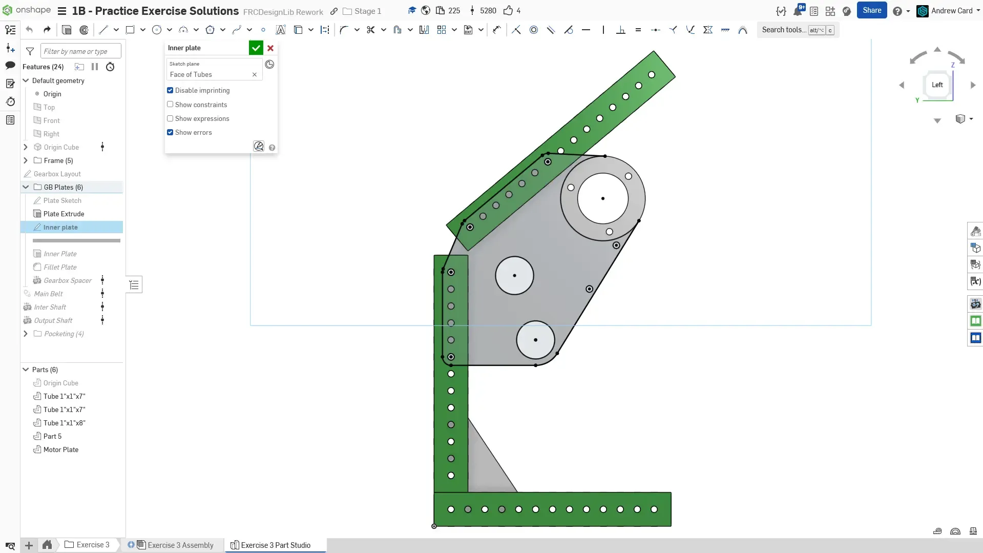
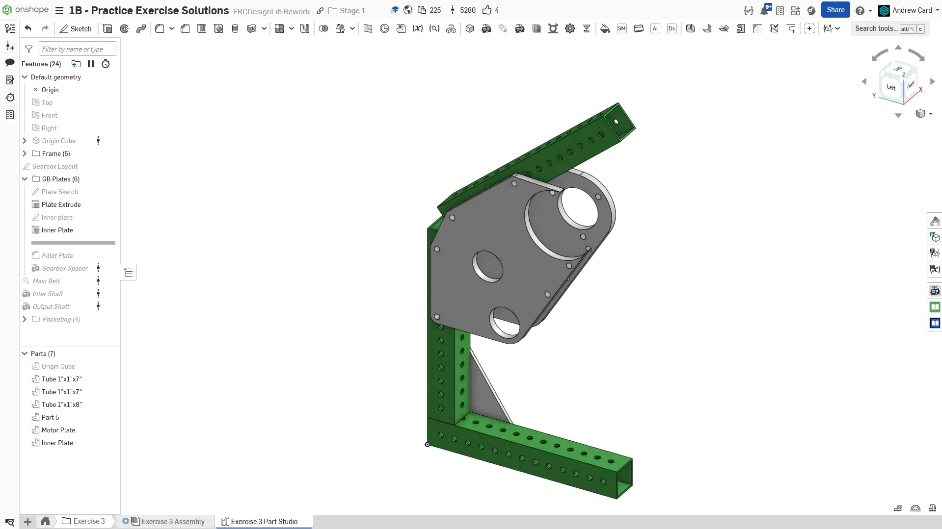
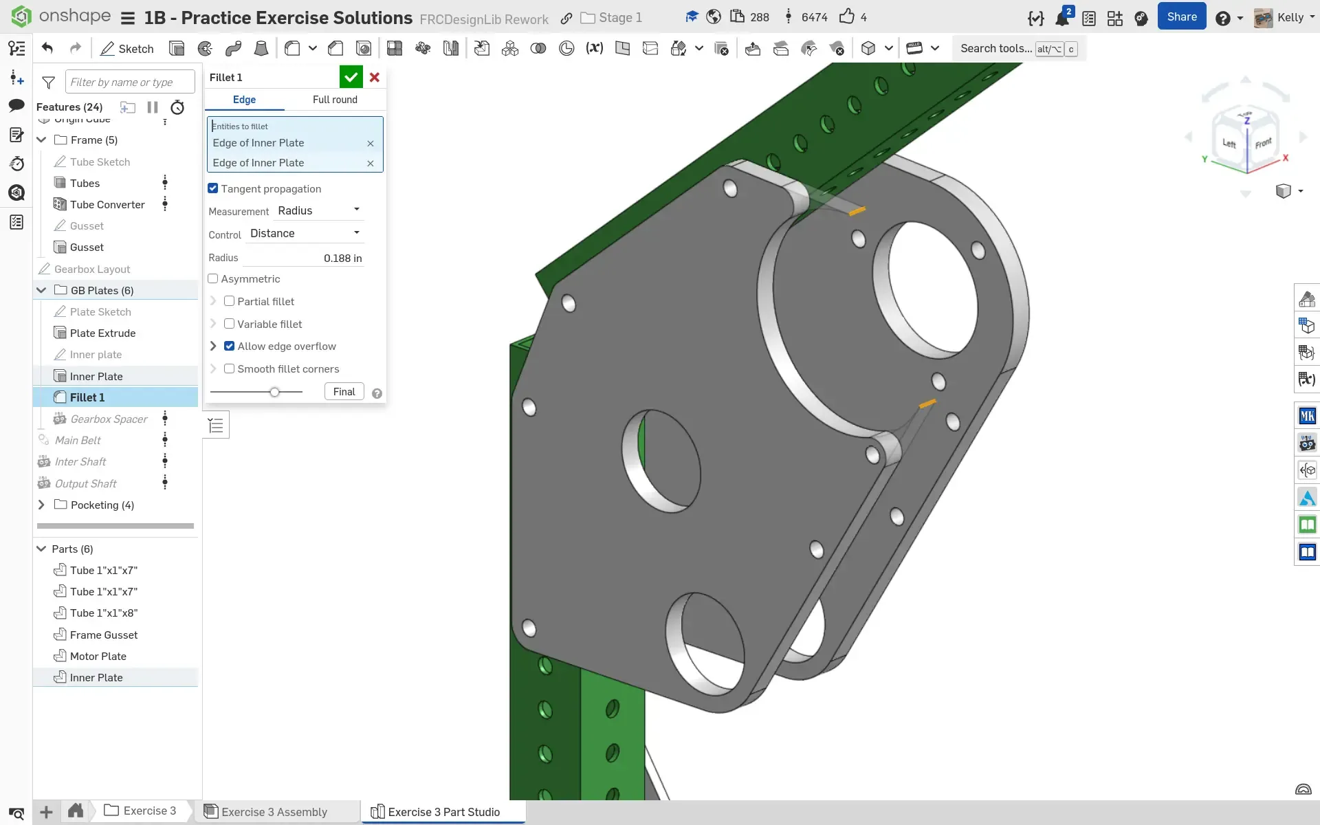
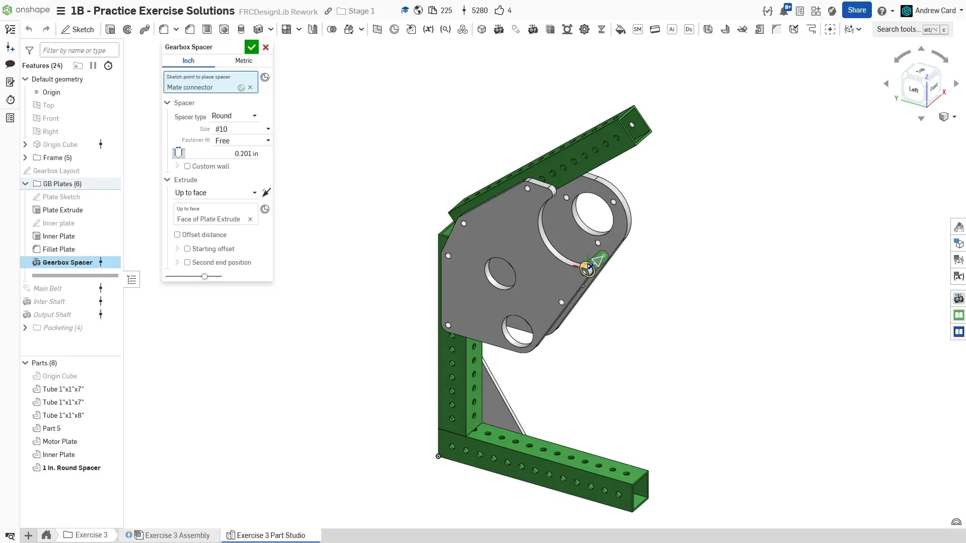
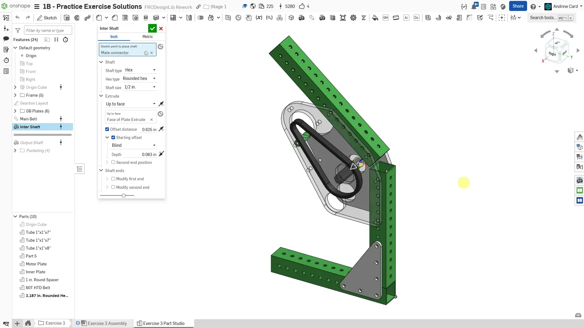
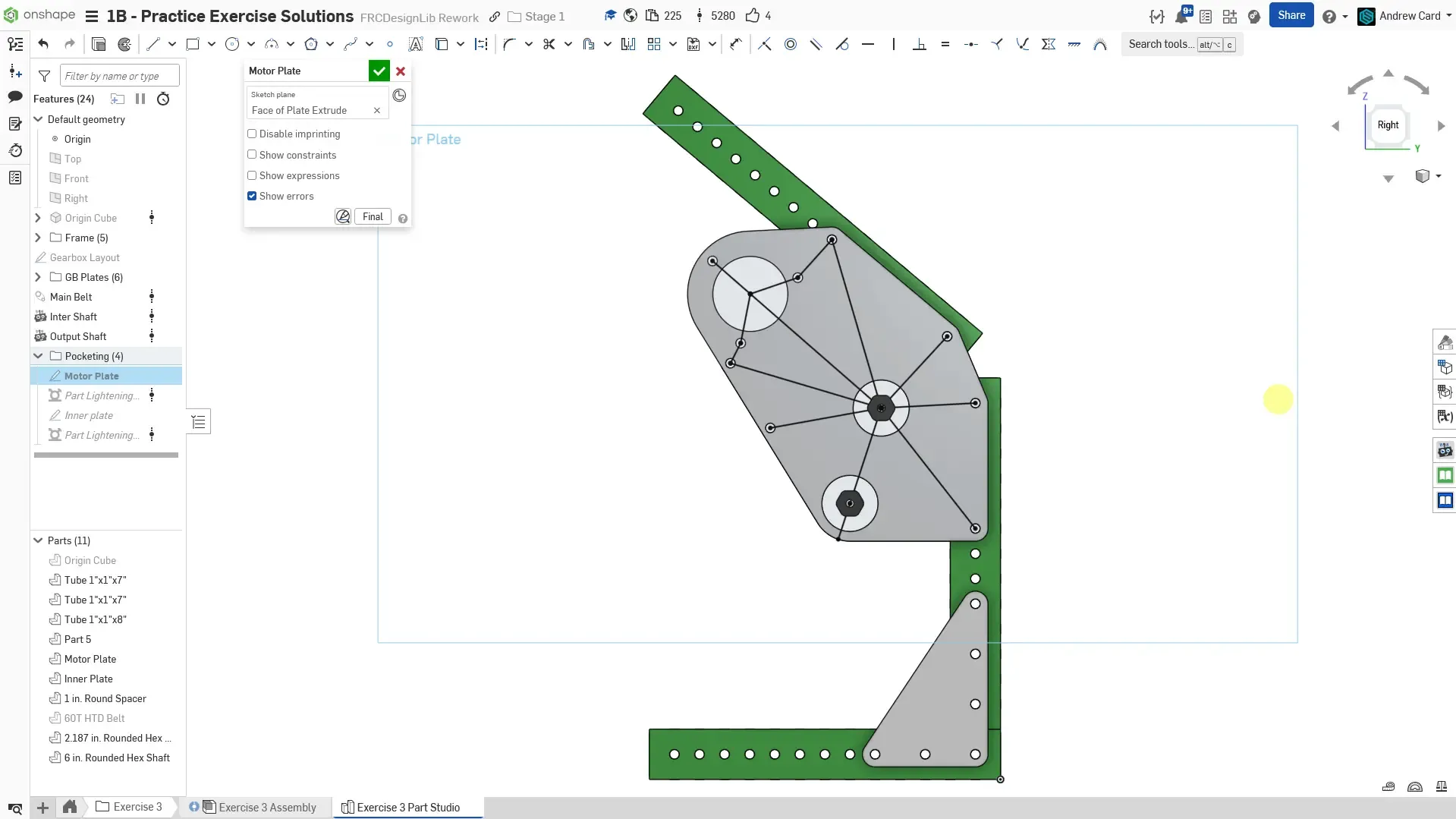
Section titled “Part Studio Instructions”Navigate to the “Exercise #3 Part Studio” tab in your copied document and follow the instructions in the slides to complete the part studio for this exercise.


Assembly Instructions
Section titled “Assembly Instructions”Now that you’ve completed the part studio, navigate to the “Exercise #3 Assembly” tab in your copied document and follow the instructions in the slides to finish this exercise.
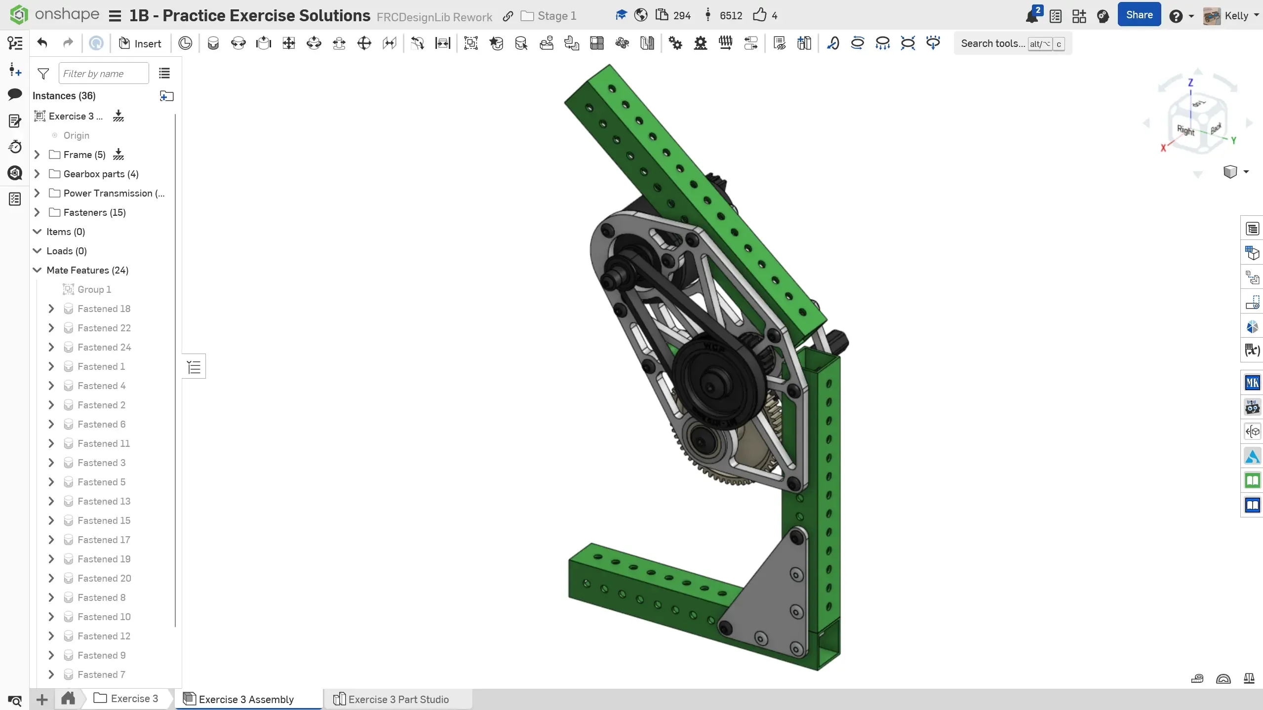
Make sure to have you and/or a more experienced member/mentor of your team review your CAD! Your assembly should have 31 instances.
In this exercise, you modeled a fairly complex gearbox that was integrated with some frame elements. At this point, you should be begin to feel comfortable with the sketching and extrude tools. You should also familiarize yourself with all the options present in the Featurescripts that you have used up until this point by playing around with different settings.
Parametric Modeling
Section titled “Parametric Modeling”To get a feel for how parametric your model is, you can try and change certain key dimensions in the layout sketches, such as the length of the tubes, angle of the tubes, length of the belt, and the size of the gears. Play around with which modifications will update smoothly and which require additional fixes in the CAD.
You may also be curious as to how things like the hole sizes, materials, etc were selected in each of these designs. You are encouraged to learn more by browsing the Design Handbook pages which contain in-depth information on a wide range of topics, or by discussing with your team and or other students and mentors on the DDS Discord.