
Design for 3D Printing
This guide serves to provide techniques and examples of 3D printing for use in FRC.
Introduction
Section titled “Introduction”Designing parts for 3D printing means understanding how to optimize your part for the way 3D printers work. Having an understanding of these ideas will help you reduce wasted material, make stronger parts, and reduce printing time.
If you’re new to 3D printing check out the Intro to 3D Printing page.
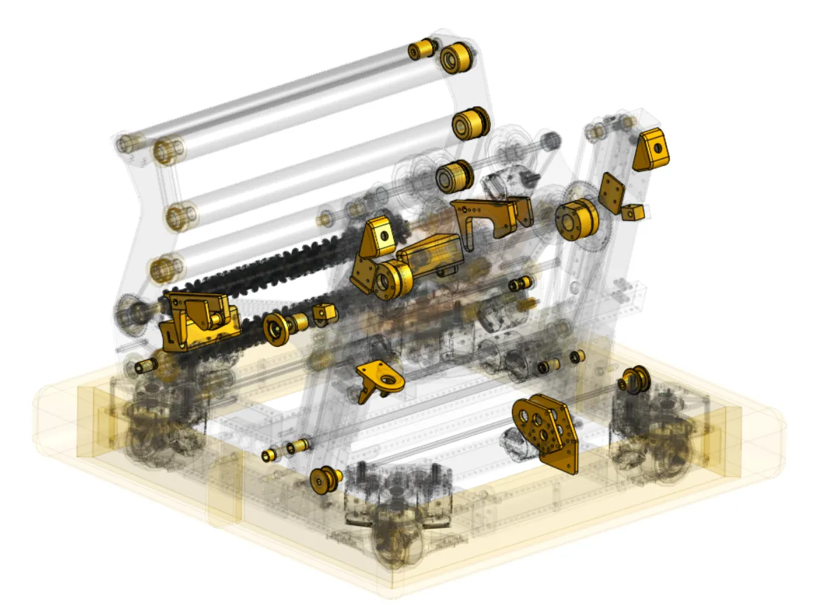
Versatility of 3D Printed Parts in FRC
Section titled “Versatility of 3D Printed Parts in FRC”3D printed parts can be used all over an FRC robot. From pulleys and sensor mounts to brackets and structural parts, 3D printing can be a powerful solution for creating almost anything.
When to Choose 3D Printing over Machining
Section titled “When to Choose 3D Printing over Machining”The first step to using 3D printing in FRC is understanding when is best to use it, in general it’s best when:
- There is no COTS part available for your needs.
- You can print a functionally equivalent solution faster or for less money than CNC milling/other processes that are available to you.
- The geometry needed would be impossible to machine on equipment you have.
- You need to prototype or test concepts quickly, especially when tuning dimensions like camera angles, game piece compression etc.
- You don’t need the part to be as strong as an equivalent metal part would be.
Part Types Covered in This Guide
Section titled “Part Types Covered in This Guide”- Spacers: Shaft spacers or offset block spacers to space out plates or parts.
- Crush Blocks: Prevent the force of tightening bolts from crushing tubes.
- Power Transmission: Print custom pulleys, gears, or sprockets.
- Custom Brackets: Create structural components or motor brackets.
- Sensor Mounts: Create mounts to attach sensors, cameras, or other components precisely to your robot chassis.
- Enclosures for Electronics: Design custom housings to protect sensitive electronics (e.g., Orange Pi, Arduino) from dust, debris, and impact.
- Tools and Jigs: Create custom tools, jigs, and fixtures to help with robot assembly, calibration, or maintenance.
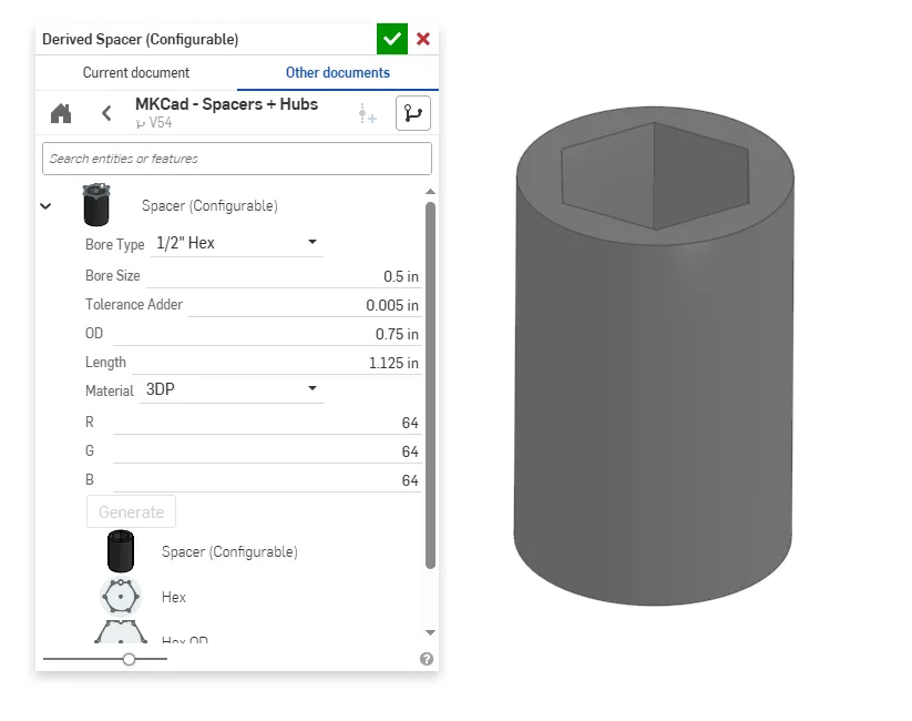
Spacers
Section titled “Spacers”One of the most straightforward use cases for 3D printing in FRC is to make custom spacers for hex shafts. Using MKCAD you can quickly make different types of spacers and customize the length. These are very easy to print at very low cost. You may notice in the dialogue box an option for additional tolerance (Tolerance Adder). 3D printers generally can produce very precise parts, but factors like thermal expansion, filament inconsistencies, poor calibration, and other error sources can lead to part dimensions that are either larger or smaller than intended. To address this we can add tolerance (gap between two parts) so that parts will fit together well. You likely will need to find the best tolerance your specific printer can achieve, but a reasonable starting tolerance will typically be about 0.004”-0.020” (0.1mm-0.5mm) depending on the type of fit desired (interference, close, clearance).
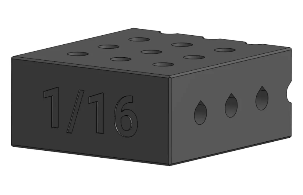
Crush Blocks
Section titled “Crush Blocks”When adding bolts through box tubes, especially 1/16” tube, the force of the bolt can crush the tube. Crush blocks help to spread out the force from tightening the bolt and prevent the tube from crushing. MKCAD has a configurable tube plug generator to quickly make crush blocks with settings for a variety of tube types and thicknesses.
Tricks for Printing Crush Blocks
Section titled “Tricks for Printing Crush Blocks”Due to the way 3D printers work through printing layer by layer, holes can end up becoming distorted when printed with their axis parallel to the build plate. This is because gravity will pull down on the hot filament as it’s printed, creating a “squished” circle hole. One solution is printing with supports, but these supports can often be difficult to get out especially in longer holes. An easy solution to this problem is to use teardrop geometry to allow for printing without supports.
Power Transmission
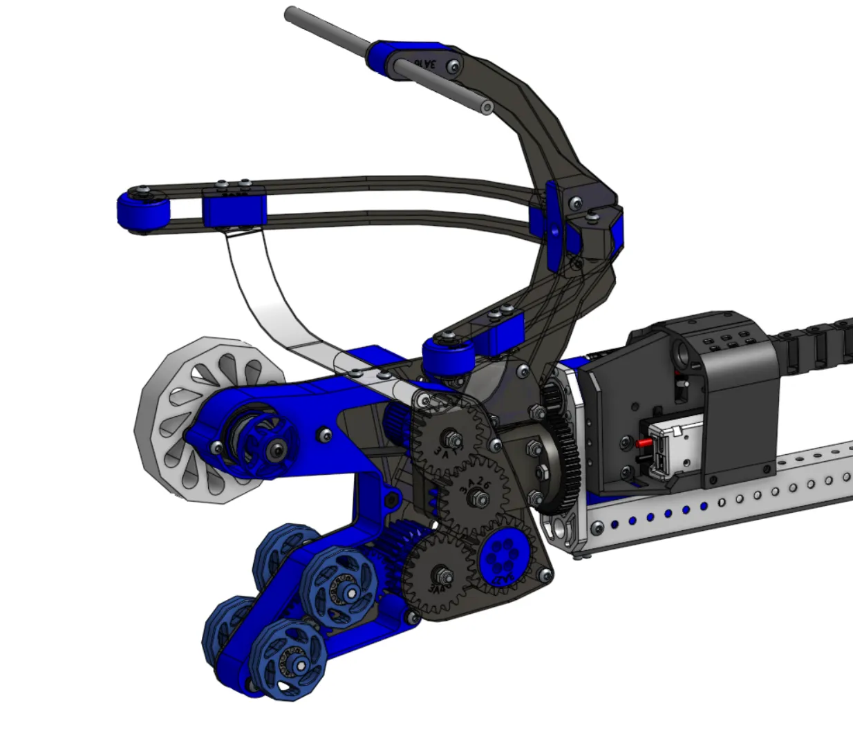
Section titled “Power Transmission”Pulleys
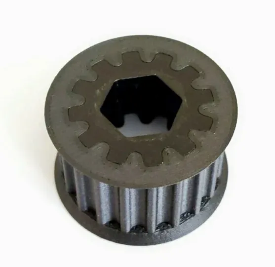
Section titled “Pulleys”Pulleys can be a great option for 3D printing. 3D printing allows you to make any number of teeth and customize how the pulley will mount to other geometry.
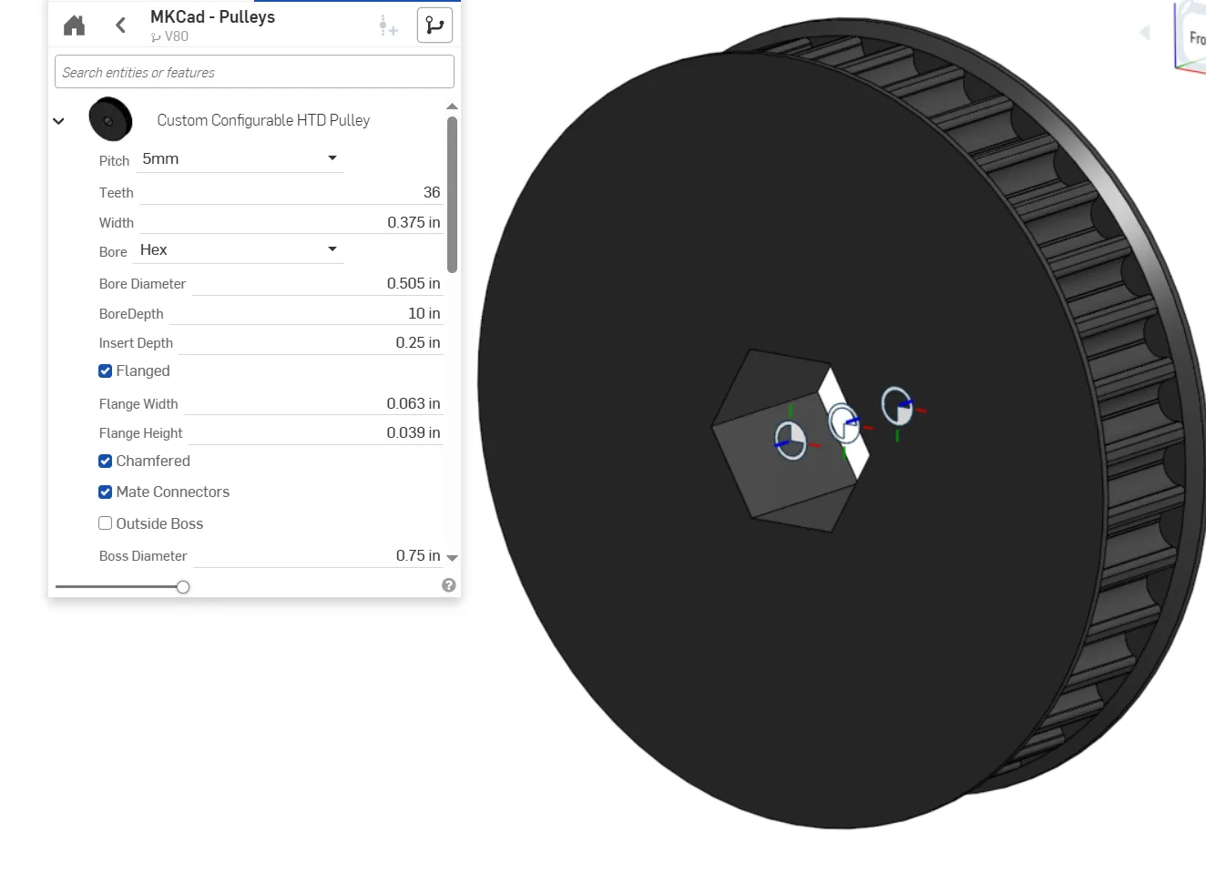
Tips for Printing Pulleys
Section titled “Tips for Printing Pulleys”Infill: Power transmission parts may need to be printed with more walls and higher infill percentage (density of the inside of the part). Depending on the use case it might even be necessary to print at 100% infill. Using lower infill will decrease print time and decrease weight, but might increase risk of the part breaking.
Hex Shaft Inserts: Compared to metal, plastic is relatively soft and can be worn down over time. High amounts of torque from a hex shaft (especially Thunderhex, which has rounded edges) can turn the hexagonal hole of a 3D printed pulley into a round hole, eventually eliminating power transmission between the shaft and pulley. One way to fix this is by using metal inserts that help to distribute the forces of the hex shaft into the printed part away from the hex bore.
Gears can be 3D printed depending on their use case. In general applications with high torque requirements are not well suited for 3D printed gears. However things like claws or secondary mechanisms can benefit from the weight savings and flexibility of 3D printing.
Tips for Gears
Section titled “Tips for Gears”Face Width: Face width refers to how much surface area is in contact between two gears. Having a larger face width reduces the stress on the gear and makes it less likely to break.
Tooth Strength: Using a lower diametral pitch (fewer teeth per pitch circle length) will make the teeth thicker, in turn making the gear stronger.
3D printed gears must be used with caution in high torque applications like motor pinions or drive gears, using 3D prints in these applications can lead to the gears becoming worn out quickly.
Custom Brackets and Structure
Section titled “Custom Brackets and Structure”3D printing is an exceptionally good solution when oddly shaped geometry is required.
Caution needs to be exercised for most structural parts, however. Parts that are prone to shock loads will be at risk of breaking or shattering.
Tips for Custom Brackets
Section titled “Tips for Custom Brackets”When designing custom brackets, it’s critical to think about how the part will be assembled on the robot. Making parts easily serviceable will make your robot more reliable during competition.
Part Orientation: Part orientation on the build plate greatly affects strength, support needs, and print time. Prints are typically strongest in the x-y plane of the printer as in the z direction the layers can delaminate (pull apart).
Material Choice: Material choice can lead to a massive difference in the performance and reliability of your part. For example, PETG offers significant improvement in impact strength and tensile strength over PLA. Polycarbonate has nearly double the tensile strength and bending strength of PLA (when properly annealed).
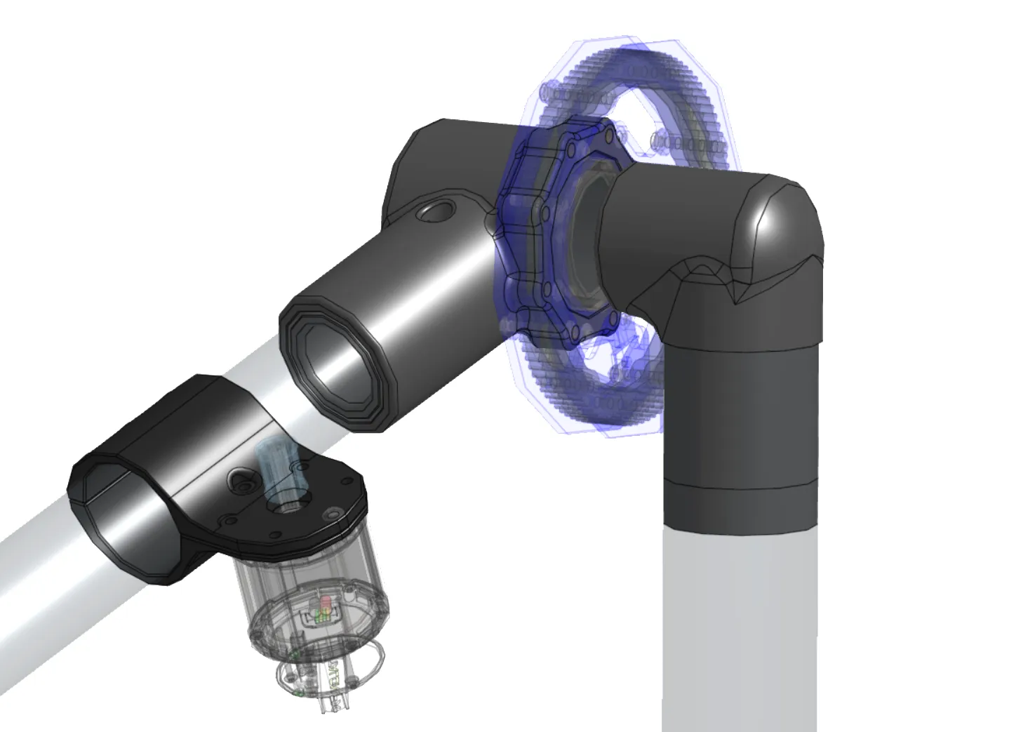
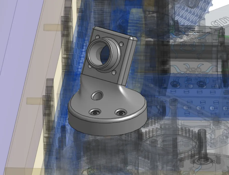
Sensor Mounts
Section titled “Sensor Mounts”3D printing is a great solution for mounting sensors or cameras as these devices often need to be located very precisely at specific angles. 3D printing makes it very easy to iterate and optimize things like camera angles to see particular April Tags or game elements.
Tips for Sensors and Strain Relief
Section titled “Tips for Sensors and Strain Relief”For sensor mounts that may get hit by game pieces or other robots, consider more durable materials, specifically materials that have high impact strength. TPU (Thermoplastic Polyurethane) is a rubber-like material that can be a great choice for very high impact resistance.
Final Notes
Section titled “Final Notes”Holes and Tolerances: Holes designed to exact CAD dimensions often print smaller due to material expansion/cooling. You can make test prints with varying hole tolerances to find optimal tolerances for your specific printer and material.
Optimize for Overhangs and Supports: An overhang is anywhere on a part that isn’t supported from below. Reducing overhangs will reduce filament wasted on support, improve the surface quality and accuracy of the part, and can reduce print time.
Fillets vs Chamfers: Fillets are a great way to make your parts smooth. However, fillets on the part surface touching the print bed can lead to part warping. Replacing the fillet with a chamfer at an angle your printer can print without supports can fix this problem.